


Introducing Mandiant's Digital Forensics and Incident Response Framework for Embedded OT Systems
Collecting and analyzing forensic data is a core component of the incident response process. This process is central to determining the existence, and subsequent scope of a compromise, the tools used by adversaries, and their capabilities. However, obtaining digital forensics and incident response (DFIR) data is not always a simple task, especially when operational technology (OT) systems are involved.
OT networks often include a variety of uncommon and sometimes obscure products that regularly leverage embedded software and firmware components. A good example of this is real-time operating systems (RTOS) that support low latency communications for precise and continuous operation of physical production environments.
As embedded systems are normally outside of the scope of traditional forensic methodologies, defenders need to identify or define tools and methodologies to gather data from these systems. A systematic approach is therefore needed to gather forensic data, build collection frameworks, set security baselines, and establish structured incident response processes.
In this post, we discuss Mandiant’s “DFIR Framework for Embedded Systems,” which is built upon Mandiant’s world-renowned incident response methodology. Our framework explains how to leverage native functionality built into OT devices and other commonly available tools to help asset owners prepare incident response efforts. To exemplify how to apply the last step of the framework, we collect data from an example remote terminal unit (RTU) in a lab setting.
Want to learn more? Enroll in our Digital Forensics and Incident Response for PLCs training course.
Why Do We Need A DFIR Framework for Embedded OT Devices?
Tools such as Mandiant’s Redline, FTK Imager, Volatility Framework, and many others have established a standard for DFIR information across IT endpoints and OT intermediary systems. Based on our experience, these tools have limited value when collecting data from embedded systems. A DFIR framework for embedded systems is needed for the following reasons:
- Gathering forensic data from OT assets helps to establish baselines for identifying anomalous activity, to investigate incidents, or assist vulnerability and asset management programs.
- Embedded OT systems often rely on non-conventional operating systems—such as VxWorks, QNX, or Windows CE—that support real-time functionalities in physical processes and environments. User interaction with an RTOS is not always simple and often limited in scope but helps us to gather forensic information.
- OT devices may be standalone, segmented, or air-gapped, often leading to a lack of visibility and/or centralized data aggregation. Manual collection of data may be required, which can be time-consuming and problematic when responding to an incident.
- Organizations that follow a structured framework to collect and analyze this information are likely to have increased visibility of critical assets. This provides opportunities to identify malicious activity and respond promptly if there is an incident.
- Organizations often track forensic data from assets even without realizing it. This happens in the form of procurement, maintenance, or other engineering processes.
Mandiant DFIR Framework for Embedded Systems
Mandiant’s DFIR Framework for Embedded Systems is comprised of three steps focused on preparation and gathering information from embedded devices during the early stages of the incident response process. Although we do provide an example for data collection, this document is not intended to make readers experts in digital forensics, but instead as a guide to understand and apply the framework to devices they operate.
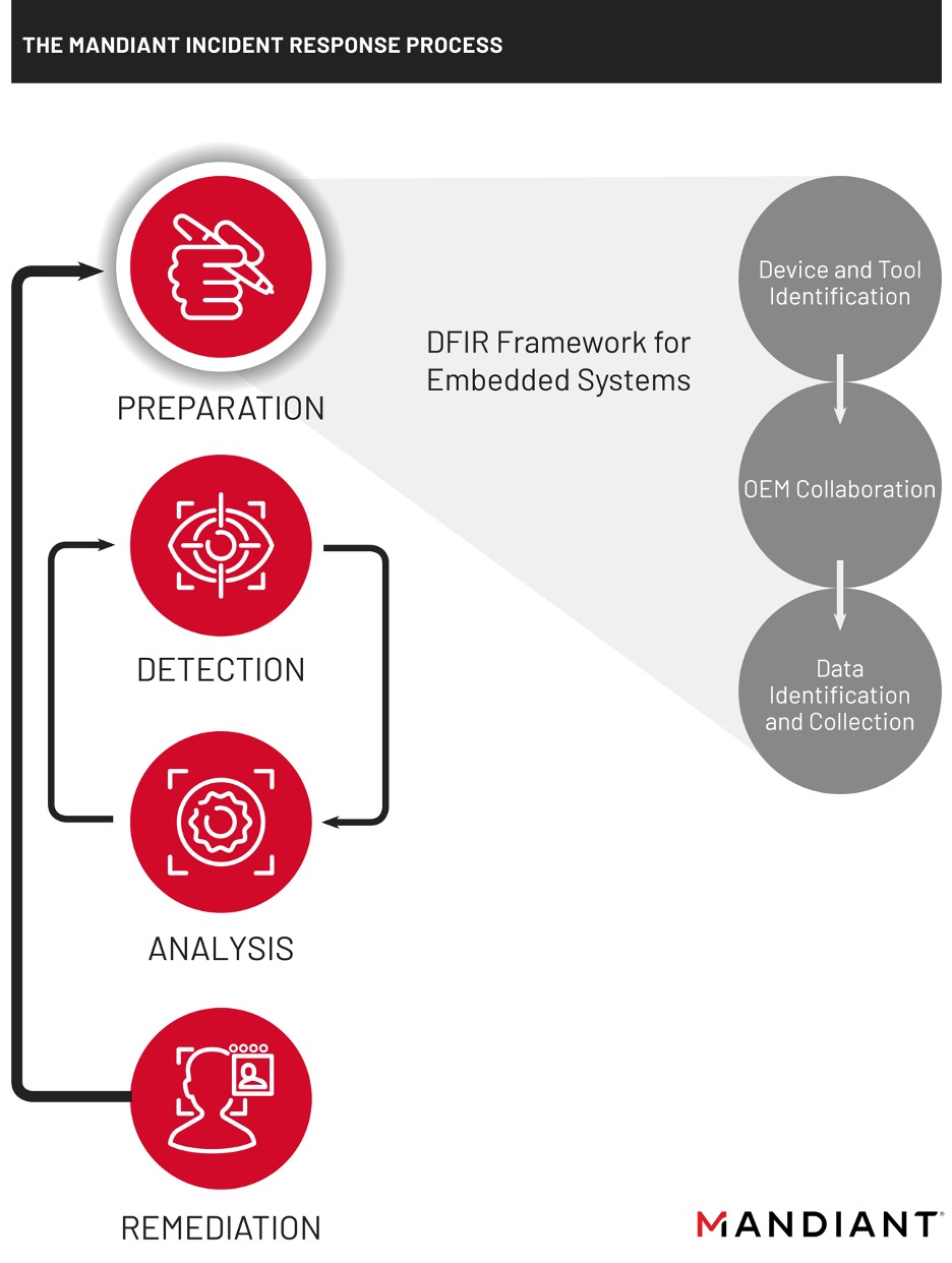
Three steps to preparation:
- Identify and document the inventory of embedded devices in an environment. Determine the tools that can be used to extract information from them.
- Collaborate with engineering team(s) and original equipment manufacturers (OEMs) to identify additional methods, tools, data sources, and vendor points of contact that may assist in supporting incident response and recovery efforts.
- Collect data that could be useful when responding to an unexpected condition or incident.
These steps share many overlaps with forensic engineering processes familiar to OT personnel, such as Root Cause Analysis (RCA) or Failure Mode and Effects Analysis (FMEA). While RCA and FMEA are focused on collecting and analyzing evidence for events affecting industrial processes, the DFIR framework for embedded systems adds the context of an adversary performing unauthorized activity through digital means. As a result, the application of this framework is most likely to succeed when supported by both cyber security and engineering personnel.
Step 1: Device and Tool Identification
In this step, engineering and security teams collaborate to identify devices to collect data from, perform physical walkdowns, and review documentation—such as technical procedures or vendor manuals. Information from field observations and product documentation yields important details on the different methods available to communicate with a device. The most common methods are:
- Software applications utilized to connect to the device for configuration, diagnostics, and troubleshooting.
- Terminal, Secure Shell (SSH), File Transfer Protocol (FTP), Telnet, or other communication protocols deployed to establish command-line access to the device.
- Enabled web server to access a graphical user interface (GUI).
- Physical ports and interfaces, such as portable media or proprietary cabling.
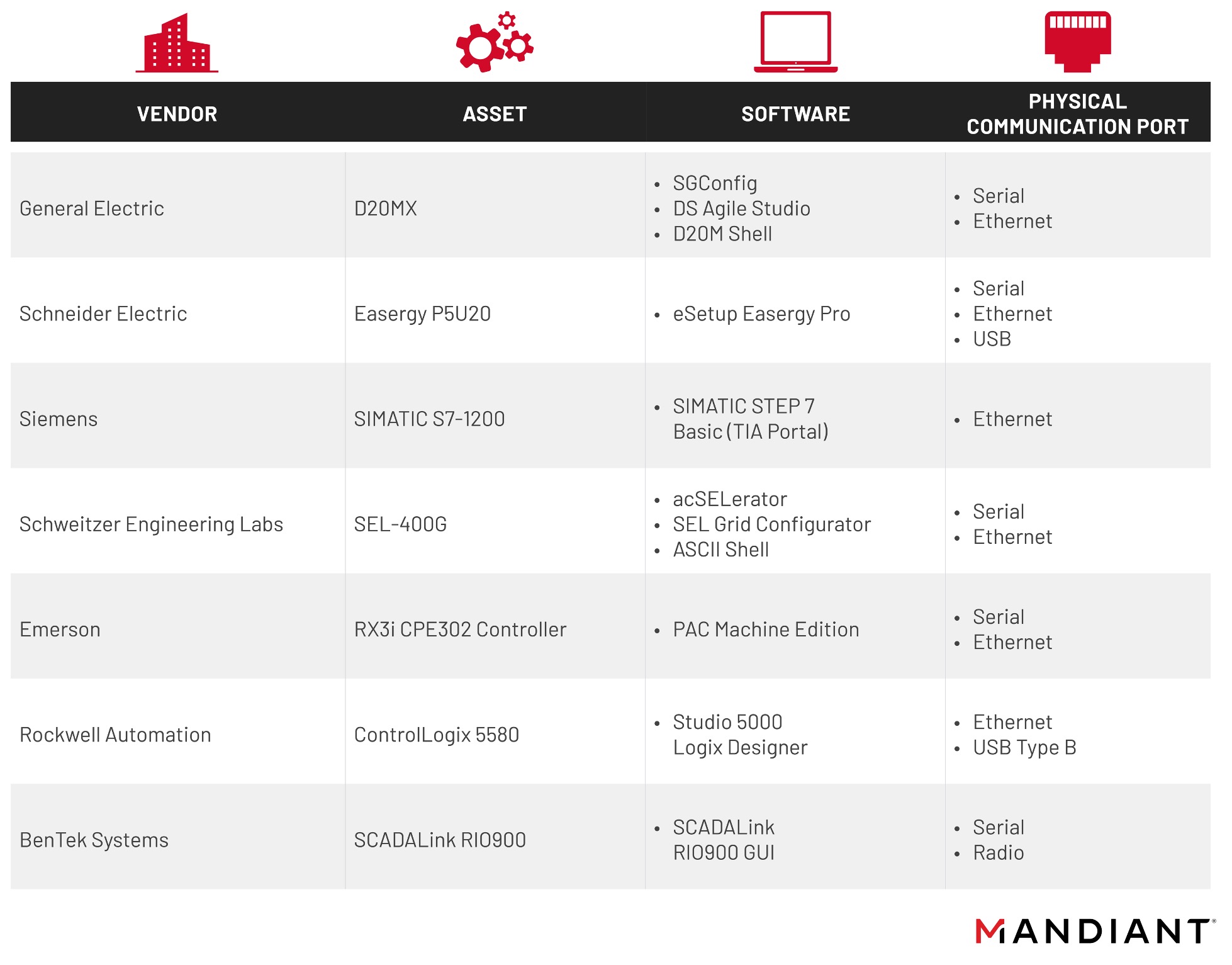
A structured record of methods for communicating with different products is necessary to sustain systematic data collection. Such documentation must describe details such as product features that are disabled or blocked due to security controls, or assets that are segmented and can only be accessed via portable media. The following table illustrates different well-known OT products and the methods of communication they rely on. This includes software from different OEM and different physical ports. In some cases, the communications listed may not be required or utilized for normal operations but can provide alternative methods of access to the device(s) when responding to an incident.
Defenders must also document supporting data resources such as locations for back-up configurations, device-specific technical procedures/vendor manuals, credentials, and individuals responsible for performing maintenance, troubleshooting, and configurations. This documentation will help to shorten the time to recovery (TTR) and prevent unnecessary delays when responding to an incident.
Step 2: OEM Collaboration
In-depth information about the functioning and features of embedded devices is most easily obtained with the support of OEMs. Vendors in charge of designing and producing embedded devices hold access to privileged information and tools that can support the forensic process. Oftentimes an operator will have to decide between asking the vendor for support or developing costly specialized tools to gather information from a device.
Given that most industrial environments use equipment from multiple OEMs, incident response preparation and training must also be supported with formal documentation on methods to communicate with devices. Gathering this data is easier with the support of OEMs that often have access to more in-depth knowledge and tools to interact with their products.
- OEMs can help to preemptively identify what data (both volatile and non-volatile) is available and how to collect it.
- OEMs often have proprietary tools or equipment that can be used to quickly collect data of value or perform analysis for devices they manufacture.
- OEMs may provide replacement devices to substitute for compromised equipment taken out of service.
- OEMs’ support may be needed if device specific software licenses are required urgently when responding to an incident.
- OEMs may have incident response guidance for asset owners to incorporate into their procedures.
Step 3: Data Identification and Collection
Stakeholders from security and operational teams (e.g. engineering, operations, and maintenance) collaborate to collect data from embedded devices based on the findings from the previous steps. Collaboration from both sides helps prevent unexpected or unintentional adverse impacts on production. Information collected during this third step makes it possible to help build or enhance asset inventories and, in some cases, help establish a baseline.
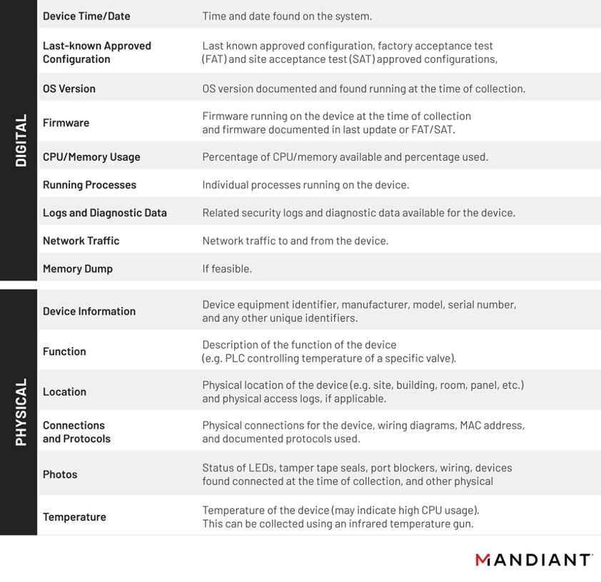
Data identification and collection from embedded OT devices should follow the same standard best practices as IT forensics—such as following the order of volatility, documenting the chain of custody, and evidence preservation. However, in this case we look for different physical and digital inputs that help us know more about the status of the device. The following list provides a non-exhaustive reference of data that we consider useful for incident response and intrusion analysis.
While there is not a single specific solution for acquiring forensic data from embedded devices, the process of becoming familiar with a device and learning how to gather information about it is consistent from one device to the next. Taking this into consideration we decided to illustrate the third step of the framework using a General Electric D20MX RTU that General Electric provided to Mandiant in support of research into DFIR for embedded devices. This research led to the creation of ics_mem_collect, a tool to perform basic VxWorks memory collection and analysis.
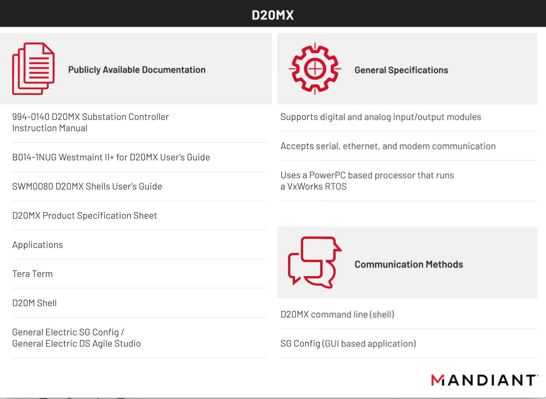
We explored two alternatives to collect information from the D20MX: a command line shell and a GUI-based proprietary application. Using both methods we obtained different types of information.
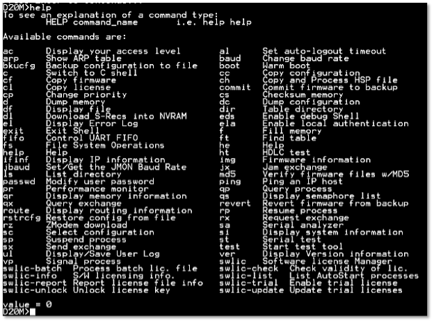
D20M Shell
An initial exploration of available commands indicated that this method would enable us to collect information for building a baseline of the device performance and perform live response when required. Information accessible via D20M shell includes device user/error logs and performance, serial and configuration data. Although we tested command-line access to the D20MX using the standard D20M shell, we highlight that the D20MX has two additional shells that provide further access and availability to data. These shells have support for other advanced capabilities such as reading and writing memory or performing packet captures.
SGConfig & DS Agile Studio
An alternative to the D20M shell is SGConfig, a proprietary GUI-based application that administrates many types of General Electric devices such as PLCs, RTUs, input/output devices, and intelligent electronic devices (IEDs).
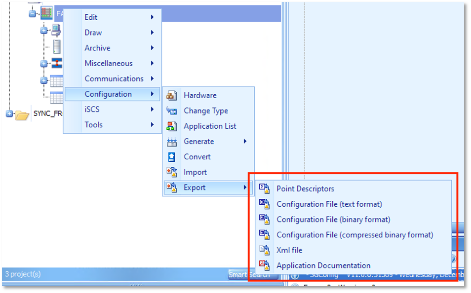
While SGConfig is primarily used to manage information associated with RTU and perform configuration actions, some of its functionalities are well suited to support incident responders. For example, SGconfig can export configuration data in a variety of forms including but not limited to text, binary, and compressed, and XML formatted data (Figure 4). Offering different file formats is useful to support analysis with different tools and methodologies.
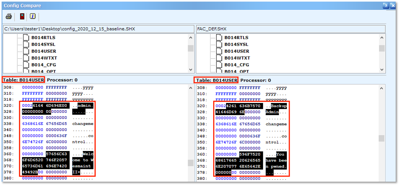
SGConfig also contains a tool to compare binary format configuration files. Figure 5 provides an example of comparing a baseline export (left) to a newer exported configuration file (right). In our example, we modified the D20MX configuration by adding a user via the SGCONFIG software. Using the SGConfig “Config Compare” feature, we were able to identify the user we created with the name “BackupAdmin.” The “Config Compare” feature identifies the configuration table that contains the modified data. In this case per the device manual, table B014USER “contains information about a user’s login name, passwords, application access and other user specific information”.
Outlook
Mandiant’s DFIR Framework for Embedded Devices proposes a systematic approach to collect and handle data from embedded devices. As such, the application of the framework should rely on collaboration between security groups, engineers, maintenance workers, and operators to collect and analyze data that support response to cyber incidents. Many of the actions suggested in the framework leverage existing processes and procedures that can also support other tasks such as disaster recovery or engineering RCA and FMEA.
Although it was out of the scope of this framework to provide various examples of data collection from different embedded products, in most cases engineering personnel may already be acquainted with tools that can help your organization to follow the steps we suggest. We also provide the following recommendations:
- Collaborate with OT teams and OEMs.
- Identify OT teams and OEM point of contacts that will support incident response efforts. This should include engineering, operations, and maintenance teams.
- Identify individuals with knowledge and expertise of the process and its embedded devices.
- Work with and communicate with these individuals to walk through the concepts and processes highlighted in this framework.
- Incorporate the processes described in this report into existing procedures.
- Include specific verbiage and sections in incident response and/or engineering procedures for cyber incidents affecting embedded industrial equipment.
- Append inventories of embedded devices, the tools and communication methods identified, and data checklists.
- Review data sources available and customize these lists where feasible, as device/environment configuration will vary amongst sites and industries.
- Create processes to update and review documentation for newly acquired embedded industrial equipment.
- Incorporate embedded industrial equipment in incident response training and exercises.
- Develop table-top exercises emulating cyber incident(s) affecting embedded industrial equipment and practice procedure execution.
- Develop awareness training for OT teams covering cyber-attacks and embedded devices.
- Walk through the process of collecting data from embedded equipment using the tools documented through the first steps of this framework.
Want to learn more? Enroll in our Digital Forensics and Incident Response for PLCs training course.
Prepare for 2024's cybersecurity landscape.
Get the Google Cloud Cybersecurity Forecast 2024 report to explore the latest trends on the horizon.